ELECTROMAGNETIC RADIATION: The Characteristics of an Electromagnetic Wave
This article is a sequel to my previous post
on ELECTROMAGNETIC RADIATION: The Use of Photodynamic Therapy As a Healing Light. In this article, I’d like to explain the speed of electromagnetic
waves, what decides their speed, electromagnetic waves in matter and electromagnetic
radiation as a wave.
Just as we all know that electromagnetic waves have a frequency f and a wavelength λ related by the simple wave formula: c = fλ. The amplitude of the wave is measured by either its electric or its magnetic component, depending on the instrument used. As with all waves, the energy carried by the wave is proportional to the square of the amplitude. As we shall see in the next paragraph, when radiation has a wavelength of comparable size to atoms and molecules, we need to think of the energy as being carried as packets or quanta, in the form of particles or photons.
THE SPEED OF ELECTROMAGNETIC WAVES
The speed of electromagnetic waves Travelling in a vacuum is the same for all frequencies and is defined as c = 2.997 924 58 × 108 ms-1 exactly.
In 1983 it was found that measurements using radio waves gave the best results and the speed of light was defined at this value. The same year, this value was confirmed by a very careful experiment using a stabilised laser working with red light. It no longer makes sense to measure the ‘speed of light’.
What decides the speed of electromagnetic waves?
In 1864, James Clerk Maxwell was considering the speed of the alternating electric and magnetic fields that define an electromagnetic wave. From theory, he worked out that the speed of these fields is determined by the electric and magnetic constants of the medium in which the waves travel. These are the force constants ε and μ.
In a vacuum, the electric field (force) constant is ε0 and is called the permittivity of a vacuum. If one charged particle is moving relative to the other, there is an additional force on both particles, the magnetic force. The magnetic field (force) constant for a vacuum is μ0 and is called the permeability of a vacuum. Air near enough a vacuum for everyday calculations. Maxwell was able to prove from theory both that electromagnetic waves other than light should exist, and also that the speed of all such waves in empty space is given by the Maxwell formula:
c = (ε0 μ0)-1/2 or c2 ε0 μ0 = 1
In a vacuum, the constants have the values:
μ0 = 4π × 10-7 Η m-1 (by theoretical definition)
ε0 = 8.85418782(7) × 10-12 F m-1 (calculated from c and μ0)
ELECTROMAGNETIC WAVES IN MATTER
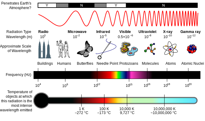
The speed of electromagnetic waves is a maximum in a vacuum and less in materials which are ‘transparent’ to the waves. As a general rule, electromagnetic waves cannot travel at all through ‘opaque’ materials containing free electrons (e.g. metals) as the waves lose so much energy to the electrons. Bound charged particles (including electrons) may also absorb energy from the waves, but do so at definite frequencies or bands of frequencies that depend on the atoms or molecules of the medium. For example, the transparency of the Earth’s atmosphere varies in different regions of the electromagnetic spectrum.
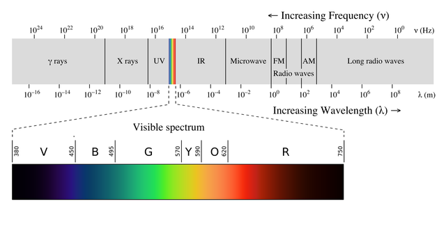
Electromagnetic spectrum with visible light highlighted. Philip Ronan, Gringer, CC BY-SA 3.0
Refraction and the speed of electromagnetic waves
We have noted that electromagnetic waves travel more slowly in a transparent medium than in a vacuum. What happens as waves enter a transparent medium in which their speed is cm is that their frequency stays the same but their wavelength gets less such that:
cm = f λm
This change in speed also causes the refraction effect – the wavefronts change direction when they enter or leave the surface of the material at other than 90° (i.e. at an angle to the normal). When a set of parallel wavefronts of single-frequency radiation is entering a transparent medium. As the leading edge enters the medium, the wave slows down but the ‘outside’ section of the front does not, so it catches up on the inside section. Inside the medium the distance between successive fronts is smaller and the direction of travel of the wave has changed. Snell’s law of refraction follows directly from this effect.
Snell’s law of refraction shows the geometry of wave refraction and proof of the sine formula. It also shows that the leading edge of a particular wavefront travels for a time t inside the medium before the rest of the front enters. Inside the medium the leading (left) edge A travels a distance cmt, whilst the right edge B travels a distance ct. As the diagram shows, simple geometry gives the result that:
Sin i/Sin r = c/cm = n (a constant)
The constant n is the refractive index and is a property of both media since it involves the speeds of electromagnetic radiation in both media. There are different refractive indices of light for some ordinary transparent materials with reference to air. The absolute refractive index is the value for light entering the medium from a vacuum (‘free space’), and is the value quoted in most reference books.
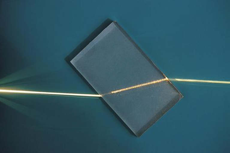
A ray of light being refracted in a plastic block. ajizai, Public Domain
Refractive index varies with wavelength
The speed of light in a given transparent medium is also likely to vary with frequency – the refractive index is different for different frequencies. Taking, for instance, the refractive index of fused quartz and crown glass varies with the vacuum wavelength of radiation between short ultraviolet wavelengths (~200 nm) and near infrared (~750 nm). Fused quartz is widely used in optical devices as it is transparent over a wide range of wavelengths.
Note that glass has a higher refractive index for light of shorter wavelengths (higher frequencies) than for longer wavelengths: light of shorter wavelength is refracted more. This is why prisms produce a spectrum from white light, with blue light deviated more red light. This effect is called dispersion.
Dispersion is a serious problem that the makers of optical instruments with lenses have to solve. Dispersion means that red light is brought to a focus further away from a positive lens than blue light is. This blurs images, an effect called chromatic aberration. Newton solved the problem for telescopes by designing one in which the light was focused by a curved mirror.
An achromatic lens can be made – a combined double lens using two different types of glass (e.g. crown and flint glass). One lens is positive and stronger than the other, negative, lens. The overall combination is positive, but the negative lens is made from a more dispersive type of glass so that the total dispersion of the combination can be made very small.
COMPETING MODELS OF LIGHT
Back in the seventeenth century, when Huygens proposed his wave model, there was another model of how light travelled (as indeed there is today). This was a model proposed by Isaac Newton. He imagined light as being made up of particles, and he developed a mechanical model to explain what was then known about the behaviour of light. The big advantage of Newton’s model was that it was easy to explain why light travelled in straight lines. It was quite easy to explain refraction too, by assuming that matter exerted a short-range force on light particles that accelerated them towards a surface, so changing their direction. It wasn’t so easy to explain such things as diffraction, and the strange fringes that could be seen due to what we now know to be the interference of waves.
The figure below shows how both Newton’s and Huygens’ models explain reflection. Both work; the two explanations of refraction, however, lead to two contrasting conclusions. According to the wave theory, light slows down when it enters a transparent medium. According to Newton’s theory, it speeds up. The critical test couldn’t be made until better techniques for measuring the speed of light were developed in the nineteenth century. Then in 1850, Leon Foucault (France, 1819-1868) measured the speed of light in water and showed that it did indeed go slower than in air.

Refraction of light at the interface between two media. Josell7, CC BY-SA 3.0
So, with care, Huygens’ theory could explain everything – but at the time it wasn’t too well worked out. In the next century Newton’s prestige – and his careful reasoning – won the contest. By 1800, thinking of light as a wave was heresy in the scientific community. But then along came Thomas Young.
Thomas Young was a terrifyingly precocious child. He could read fluently at the age of two. He qualified as a doctor at the age of 19 and at 27 was appointed a professor at the new Royal Institution in London, later moving to work at the Royal Society. He studied the eye and vision, and found that the best model for optics was to think of light as a wave. For example, he used the principle of superposition to explain the colour effects seen in thin films of oil on water. He was jeered at for this and went back to medical studies. In his spare time, he showed how to decipher the ancient Egyptian writing (hieroglyphs). But his wave theories gained support in France from younger physicists, and he returned to the study of light. His experiments on the interference of light provided firm evidence for its wave nature. However, evidence for a theory is often not enough. Even after the evidence for a wave theory became overwhelming it wasn’t accepted until the older ‘particle supporters’ died out. This is not an uncommon way in which radical new theories get accepted!
ELECTROMAGNETIC RADIATION AS A WAVE
So far in this article, we have thought of electromagnetic radiation as a wave. But physics in fact uses three main models of light – a straight line ‘ray’ model, a particle (photon) model, and the wave model which I shall talk about in the next post.
THE DIFFRACTION OF WAVES
The figure below shows a set of parallel water waves passing through a small gap in a barrier. The waves spread out after passing through. This spreading out is called diffraction and is a key to distinguishing wave behaviour from particle behaviour.
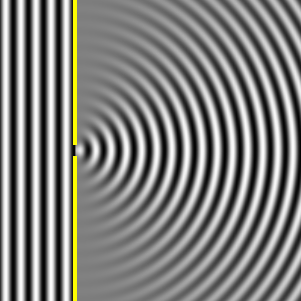
Diffraction of a plane wave when the slit width equals the wavelength. Lookangmany, CC BY-SA 3.0
HOW WAVES MOVE FORWARD
We see that a wave crest such as a single ripple moves forward and keeps its direction. At the crest of the water wave there is a volume of water temporarily lifted above its normal level. Imagine raising just a small part of a water surface (e.g. by touching it and lifting your finger away). You would expect, correctly, that it would immediately collapse in all directions. The water surface then oscillates up and down and a circular pulse moves away from the site of the initial disturbance.
Why does the ring of raised water in the pulse (a circular crest) keep going with the same shape? To answer this – and to explain diffraction properly – we have to use two ideas proposed by Jan Christian Huygens (Holland, 1629-1695). One is known as Huygens’ principle, the other is the principle of superposition.
In
my next article, I shall be shedding more light on Huygens’ principle and his
principle of superposition amongst other interesting aspects of electromagnetic
waves such as coherence, image formation, diffraction grating, etc. But, till
then, I still remain my humble self, @emperorhassy.
REFERENCES
https://www.nasa.gov/directorates/heo/scan/spectrum/txt_characteristics_spectrum.html
https://en.wikipedia.org/wiki/Electromagnetic_spectrum
https://byjus.com/physics/characteristics-of-em-waves/
https://en.wikipedia.org/wiki/Electromagnetic_radiation
http://electron6.phys.utk.edu/optics421/modules/m1/emwaves.htm
https://www.physicsclassroom.com/mmedia/waves/em.cfm
http://www.pas.rochester.edu/~cline/P114/Chapter16.pdf
https://en.wikiversity.org/wiki/Electromagnetic_wave
https://en.wikipedia.org/wiki/Refractive_index
https://www.britannica.com/science/light/Early-particle-and-wave-theories
https://en.wikipedia.org/wiki/Huygens%E2%80%93Fresnel_principle
This post has been voted on by the SteemSTEM curation team and voting trail. It is elligible for support from @curie and @utopian-io.
If you appreciate the work we are doing, then consider supporting our witness stem.witness. Additional witness support to the curie witness and utopian-io witness would be appreciated as well.
For additional information please join us on the SteemSTEM discord and to get to know the rest of the community!
Thanks for having added @steemstem as a beneficiary to your post. This granted you a stronger support from SteemSTEM.
Thanks for having used the steemstem.io app. You got a stronger support!
Hi @emperorhassy!
Your post was upvoted by Utopian.io in cooperation with @steemstem - supporting knowledge, innovation and technological advancement on the Steem Blockchain.
Contribute to Open Source with utopian.io
Learn how to contribute on our website and join the new open source economy.
Want to chat? Join the Utopian Community on Discord https://discord.gg/h52nFrV