Elektronikprojekt Teil 6 / Electronics project part 6
Hallo Elektronikfreunde.
Der Ersatzschalter (der graue in Bild01) ist eingetroffen und die gute Nachricht, er passt in den Frontplattenausschnitt.
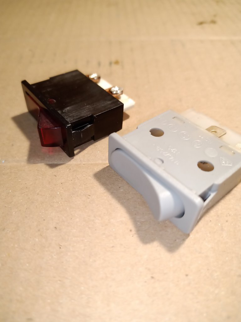
Bild 01 Ersatzschalter
Trotzdem bin ich nicht richtig zufrieden. Der neue Schalter ist nur 1polig und ich würde die Netzspannung lieber 2polig trennen.
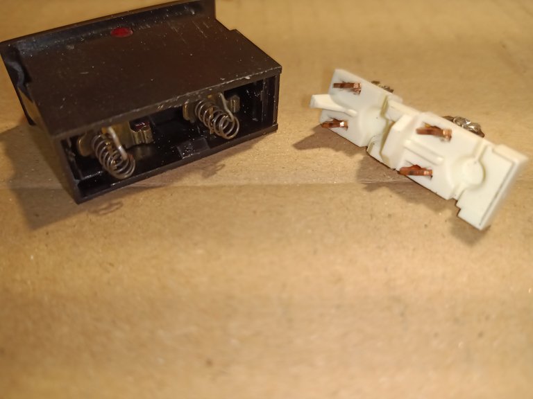
Bild 02
Deshalb habe ich mal den defekten Schalter auseinandergenommen (Bild02). Da ist erstaunlich wenig drin. Im schwarzen Teil zwei Metallwippen mit Feder und im weißen Teil, vier Metallkontakte die im Plastik eingesteckt und dann die Kontaktflächen, welche leicht verdreht wurden. Erstaunlich das diese kleinen Kontaktflächen bis zu 10Ampere schalten sollen. Unter dem roten Kippschalterteil steckt dann noch eine Glimmlampe mit Vorwiderstand.
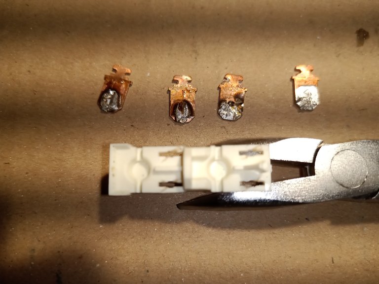
Bild 03
Tatsächlich, so wie ich es schon vermutet habe. Durch die Lötwärme hat sich das weiße Plastik verformt und die Kupferkontakte haben keine stabile Verbindung zu den Schaltwippen im schwarzen Schalterteil.
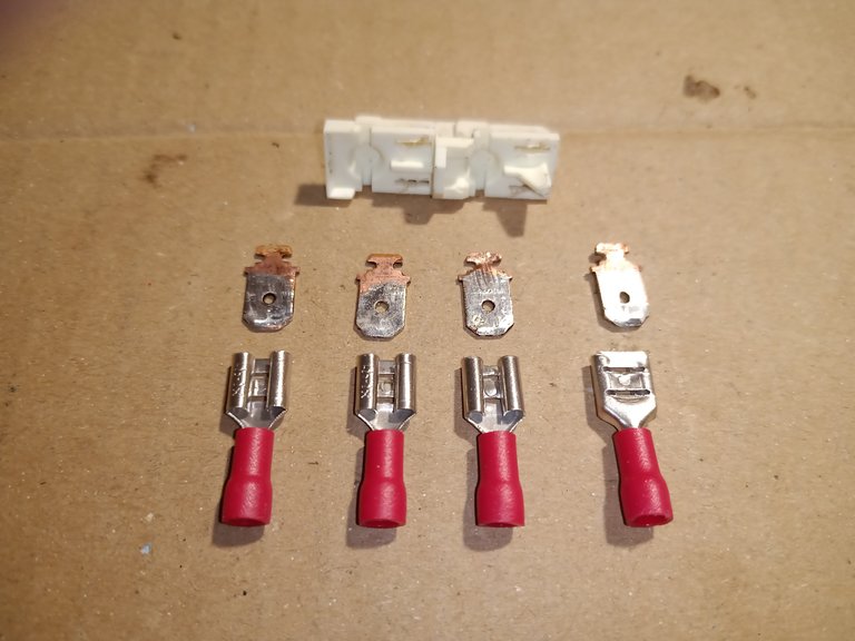
Bild 04
Deshalb erstmal die Kupferkontakte verzinnt und das überschüssige Lötzinn entfernt, so dass die 6,3mm Steckkontakte problemlos aufgeschoben werden können. Dann mit Stahlwolle die Kontakte gereinigt und mit Kontaktspray behandelt und wieder ins weiße Plastikteil eingesetzt. Dazu habe ich die Kupferkontakte leicht erwärmt, damit sie sich ein wenig in die Plaste einschmelzen konnten und anschließend durch leichtes Verdrehen gesichert.
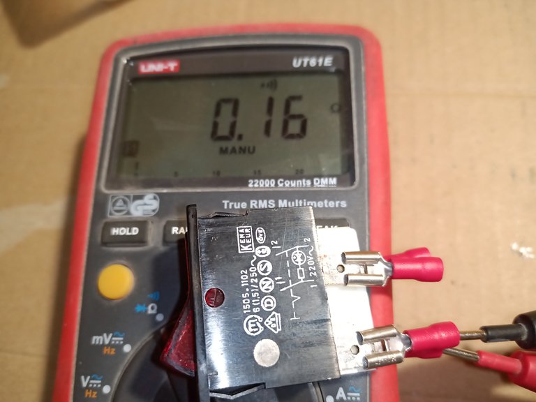
Bild 05
Das Ganze zusammengesteckt und mit dem Durchgangsprüfer die Kontakte geprüft. Wie im Bild 05 zu sehen, der Übergangswiderstand liegt bei 0,16 Ohm. Das ist so in Ordnung.
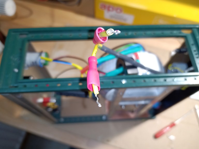
Bild 06
Nun kann ich die Netzseite komplettieren.
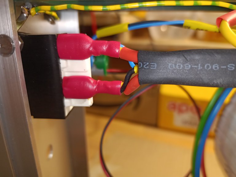
Bild 07
Wie schon im vorhergehenden Teil beschrieben, müssen alle Verbindungen berührungssicher ausgeführt werden.
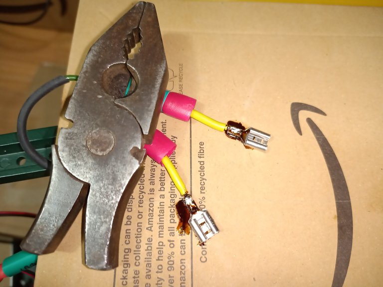
Bild 08
Ich habe vollisolierte Kabelschuhe benutzt und zusätzlich noch Schrumpfschlauch.
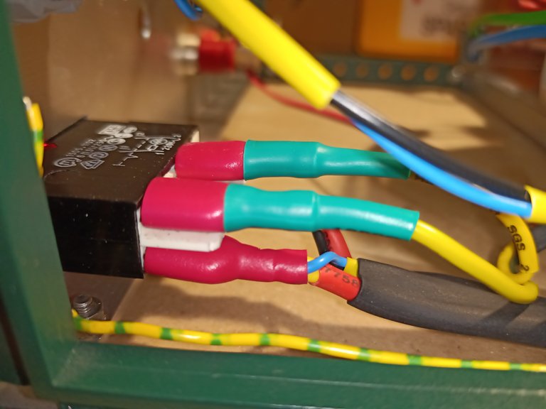
Bild 09
Hier im Bild die Anschlüsse des Schalters vollisoliert,
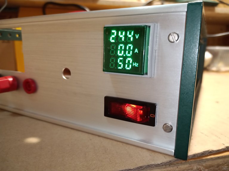
Bild 10
Und die Frontplatte mit Schalter und Netzanzeige.
Vielen Dank für das Lesen meiner Beiträge
Fortsetzung folgt …….
googke translator
Hello electronics enthusiasts.
The replacement switch (the gray one in picture 01) has arrived and the good news, it fits into the front panel cutout.
Fig. 01 Replacement switch
Still, I'm not really happy. The new switch is only 1-pole and I would prefer to disconnect the mains voltage with 2-pole.
Fig. 02
That's why I took apart the defective switch (Fig. 02). There is surprisingly little in there. In the black part two metal rockers with spring and in the white part, four metal contacts inserted in the plastic and then the contact surfaces, which were slightly twisted. Amazing that these small contact areas should switch up to 10 amps. Under the red toggle switch part there is a glow lamp with a series resistor.
Fig. 03
In fact, as I suspected. The white plastic has deformed due to the heat of the solder and the copper contacts have no stable connection to the rocker switches in the black switch part.
Fig. 04
Therefore, the copper contacts are tinned and the excess solder is removed so that the 6.3 mm plug contacts can be easily pushed on. Then the contacts were cleaned with steel wool and treated with contact spray and put back into the white plastic part. To do this, I warmed the copper contacts slightly so that they could melt a little into the plastic and then secured them by turning them slightly.
Fig. 05
The whole thing put together and checked the contacts with the continuity tester. As can be seen in Figure 05, the contact resistance is 0.16 Ohm. That's OK.
Figure 06
Now I can complete the web page
Picture 07
As already described in the previous section, all connections must be made safe from touch.
Figure 08
I used fully insulated cable lugs and also shrink tubing.
Figure 09
In the picture, the connections of the switch are fully insulated,
Figure 10
And the front panel with switch and power indicator.
Thank you for reading my posts
Sequel follows …….
Du hast ein Upvote von mir bekommen, diese soll die Deutsche Community unterstützen. Wenn du mich unterstützten möchtest, dann sende mir eine Delegation. Egal wie klein die Unterstützung ist, Du hilfst damit der Community. DANKE!