Ben Eater 6502 Kit — Day 20
The ordered spare parts have arrive and not a minute too late. The poor EEPROM looks pretty beaten:
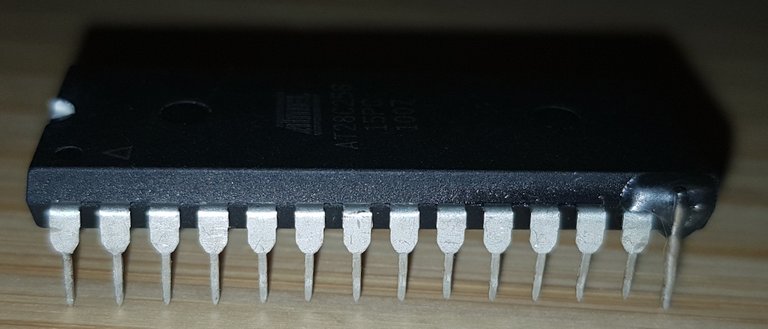
One leg broken off at the case
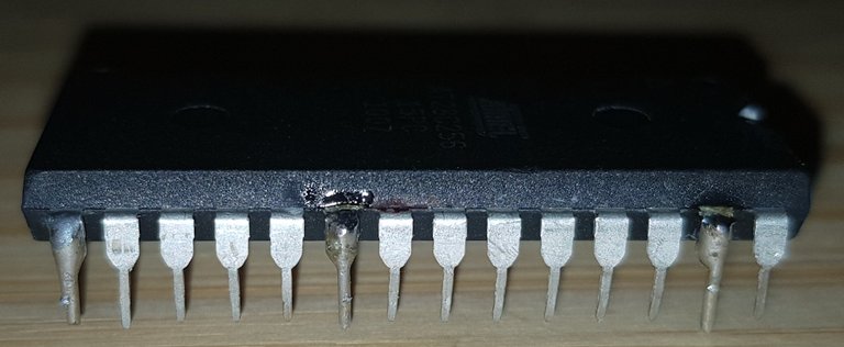
Three legs broken on the opposite side
I ordered a machined socket and two spare EEPROM. The pins of the machined sockets are very sturdy any won't break off. I plan to keep the EEPROM in the socket at all time so the EEPROM won't take any damage.
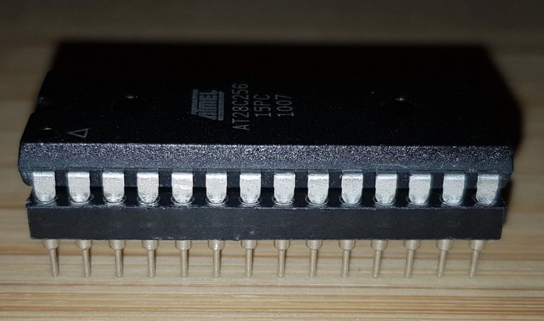
New EEPROM nicely protected
I also put a dot of white paint on the left side of the chip. One time I put the chip in the wrong way. Things got heated pretty quickly.
EEPROM with high visibility white dot.
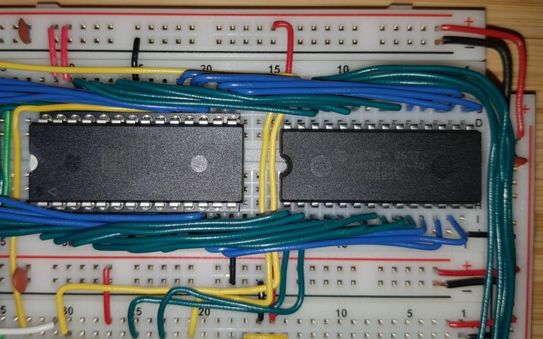
EEPROM with socket on the breadboard
I also ordered a second switch so I can switch between the crystal oscillator and the clock module without any error prone jump wire.
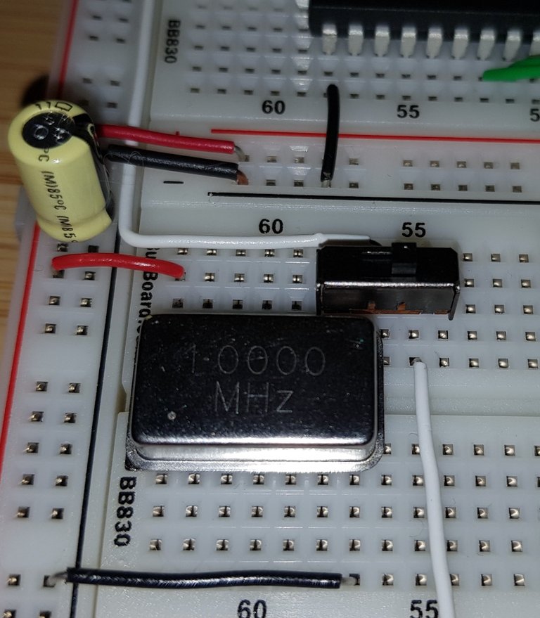
second clock switch
Now I'm ready for development of the decimal number output. I noted that Ben Eater is using null terminated C strings. As someone who had an Atari 400 as a teenager I know that almost no one used C string on a 6502. C strings are cumbersome and slow to use as well very error prone. The only advantage of C strings is that they can be of unlimited length. Which on an 8bit computer is of very limited use and for all practical purpose strings are limited to 256 bytes on a 6502 as the index register are only 8 bit.
And for up to 256 bytes traditional strings where one remembers the current and maximum length are far more convenient to use. I also moved some of the variables into the zero page using the CA65 ability to automatically assign memory addresses:
.segment    "ZEROPAGE"
;;
;   Storage to perform the division needed for decimal output
;
Value:     .res 2     ; Dividend
Mod10:     .res 2     ; Remainder
Subtract:   .res 2     ; Subtract

.segment    "DATA"

;;
;   Text buffer for numeric output
;
Text:     .res 5
Text_Len    =  * - Text
The way I did it it is to keep the position of the current character in the Y register while the subtraction low byte is kept in the zero page. I considered using the stack but that would have needed some complicated cleanup.
To make the code more reusable I moved everything into a subroutine using a CA65 procedure. This makes all the labels in the procedure local so I won't need to prefix them with “lcd_” or such likes.
Lastly I'm using modern 65C02 features as well as the generic macro package to make the code more compact. So this time it's Ben who over engineered his code.
.segment    "CODE"

.proc     Print_Decimal
    PHX     ; Save X and Y register to stack
    PHY
    LDY  #(LCD::Text_Len) ; We start at the end of the text buffer

Divide:     DEY     ; And store the characters descending
    STZ  LCD::Mod10  ; Initialize remainder with zero
    STZ  LCD::Mod10 + 1
    LDX  #16
    CLC

Digit:     ROL  LCD::Value  ; Rotated dividend and remainder
    ROL  LCD::Value + 1
    ROL  LCD::Mod10
    ROL  LCD::Mod10 + 1

    LDA  LCD::Mod10  ; Subtract 10 from Remainder
    SUB  #10
    STA  LCD::Subtract  ; Temporary store low byte of subtraction
    LDA  LCD::Mod10 + 1
    SBC  #0
    BCC  Ignore   ; Skip if remainder was smaller then 10

    STA  LCD::Mod10 + 1  ; Store subtracted value in remainder
    LDA  LCD::Subtract  ; restore low byte of subtraction
    STA  LCD::Mod10

Ignore:     DEX     ; Continue for 16 rotations.
    BNE  Digit

    ROL  LCD::Value  ; one last rotation for dividend only.
    ROL  LCD::Value + 1
    LDA  LCD::Mod10  ; our next character is in remainder
    ADD  #'0'
    STA  LCD::Text,Y

    LDA  LCD::Value  ; stop when dividend is zero
    ORA  LCD::Value + 1
    BNE  Divide

; Print output. Note that Y points to the first character.

Loop:     LCD_Print {LCD::Text,Y} ; Write next character to Display
    INY
    CPY  #(LCD::Text_Len) ; Repeat loop until Y ≥ message length
    BLT  Loop

    PLY
    PLX
    RTS
.endproc
I also added a convenience macro to make calling the subroutine easy.
.macro     LCD_Decimal Number
    PHA
    LDA  Number   ; Initialise parameter
    STA  LCD::Value
    LDA  Number + 1
    STA  LCD::Value + 1

    JSR  LCD::Print_Decimal

    PLA
.endmacro
With all of that the actual main program is very short:
.macpack    generic
.include    "VIA.inc"
.include    "LCD.inc"

.segment    "RODATA"

Number:     .word   1729

.segment    "CODE"

Do_RES:     LDX     #$FF
        TXS

        VIA_Set_A   #%11100000      ; Set top 3 pin as output
        VIA_Set_B   #%11111111      ; Set all pins as output

        LCD_Control #%00111000      ; Set 8-bit mode; 2 line display; 5×8 font
        LCD_Control #%00001110      ; Display on; cursor on; blink off
        LCD_Control #%00000110      ; Increment and shift cursor; don't shift display
        LCD_Control #%00000001      ; Clear Display

        LCD_Decimal Number          ; Print number in decimal

        STP                 ; Stop Processor

Do_NMI:     RTI

Do_IRQ:     RTI

.segment    "HEADER"
.word       Do_NMI
.word       Do_RES
.word       Do_IRQ
As you can see: no memory addresses are directly assigned. Assigning memory is all handled by the LD65 linker.
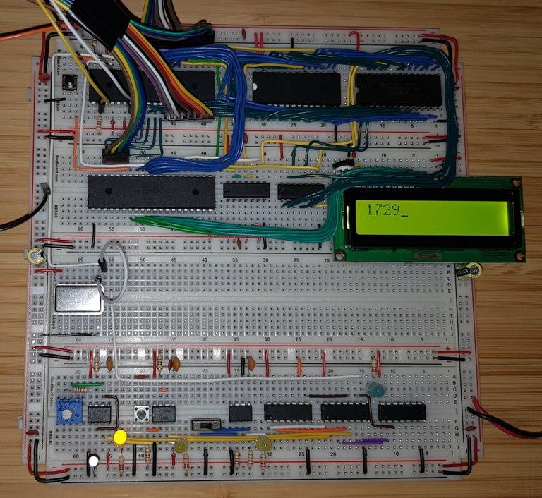
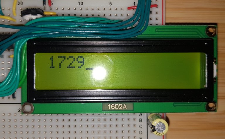
Output of finished program
You find the source code for the LCD macro on GitLab: 6502Tutorial — Kit/Library