New guitar amplifier project, the PE-30, part 2
Hello, and welcome to my page!
In part 1 of this series, I talked a bit about the amplifier that is the basis for this amp rebuilding project, and getting started on the rebuild. If you would like to read part 1, here is the link to it.
https://steemit.com/guitar-amp/@amberyooper/a-new-guitar-amplifier-project-the-pe-30-part-1
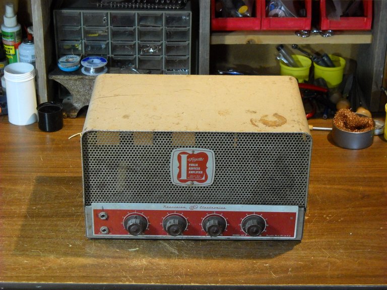
This is the late 1950s amplifier that will become a guitar amp when I'm done with it.
At the end of the last post, I had gotten all of the parts out of the amplifier in the areas where I have to change the circuits for the tubes that I'll be using. The next thing to do was to start building the new circuits to guitar amp configuration. When I rebuild one of these old amplifiers, I usually use circuit designs that are similar to existing guitar amp designs instead of trying to invent something completely different.
Most of the existing tube powered guitar amplifier designs share certain characteristics in circuit design. The main differences that you see in guitar amps is the design of the tone circuitry, with most designs falling into 2 categories with a lot of variations in 1 of the 2 categories, and the other design, being less amenable to changes, usually is about the same in the amplifiers that use it.
The older Ampeg guitar amplifiers use the second design of tone controls, consisting of a bass and treble control, both of which can add as well as cut the tone that they control. The more common tone controls such as the ones on the Fender and Marshall amplifiers can only cut the tone due to the design of the circuit. The advantage of the Fender and Marshall type circuit is that they can have 3 tone controls, base, midrange, and treble. You can get a wider range of tone changes with 3 controls rather than 2.
For this amp build, I chose to use an Ampeg type circuit, mostly based on the type of tubes that I can use in the existing tube sockets. A lot of the Ampeg amps of the 1960s used the 8 pin octal preamplifier tube, the 6SL7. Most of the other designs of the 1960s and 70s used a 9 pin miniature preamp tube such as the 12AX7. Since I didn't want to change the sockets that are in the amp, I decided to use the 8 pin preamp tubes.
The first thing that I decided to build was the circuit for the preamp tube that drives the power output tubes. The Ampeg design uses a "split load inverter" circuit for the driver tube, so that's what I assembled. This picture shows it mostly assembled.
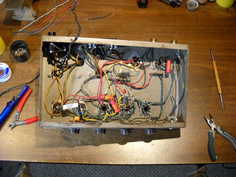
This amp was originally built using what's called point to point wiring, there's no circuit board to put the parts onto. Many of the older amps are built with point to point construction. I didn't want to have to put in a circuit board, so I decided to wire the amp point to point. The main challenge to that is finding connections to attach the parts to. I had to put several terminal strips in the amp chassis to have places to connect the various resistors and capacitors for the circuits.
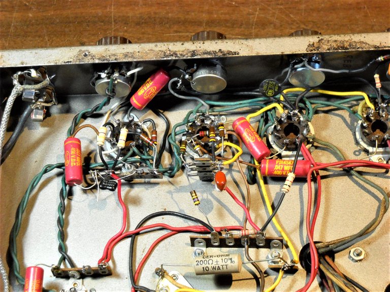
Once I was done building most of the driver circuit, I started on the tone control circuits. That circuit is a group of resistors and capacitors that are arranged to split the signal into 2 parts to provide for controlling the treble and bass frequencies separately. With point to point construction, half the components are attached directly to the controls, and most of the other parts are connected to the pins on the tube socket. At the point where this picture was taken, there were several parts for the circuit that I still didn't have a place to connect. You can't just put them anywhere, there are specific connections that have to be made.
The tube socket to the left in the picture is for the tone control amplifier tube, the socket next to it is the driver tube socket. The 2 sockets to the right of that are the power tube sockets. At this point, the circuits start to look like an incomprehensible mess.
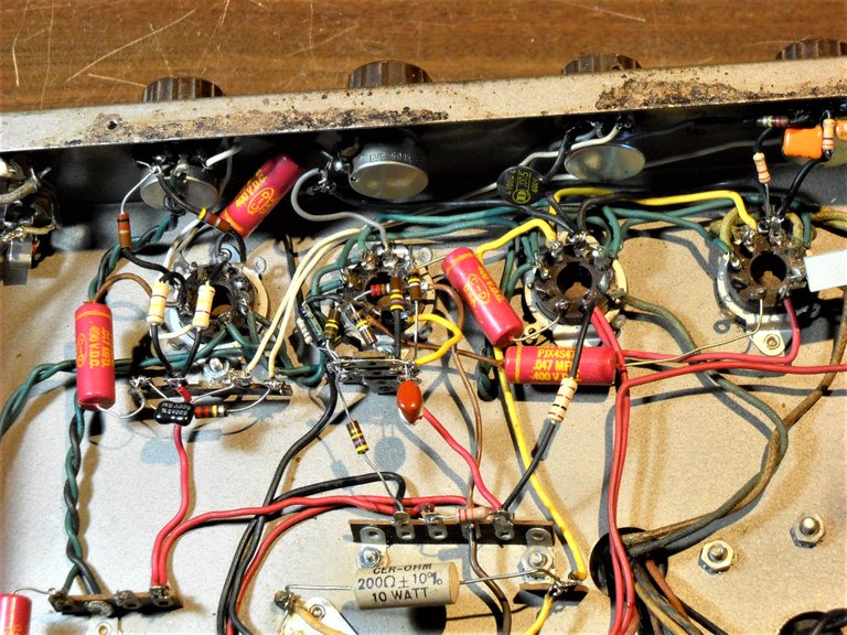
I ran out of places to connect parts to and has to add another terminal strip to finish the tone control circuit. I also had to move a couple of resistors to a different ground point so that I could use a previously occupied connection point to finish the circuit. This is as far as I've gotten on the amp build so far.
The next thing that I have to do is to build the first stage preamplifier circuit for the guitar input. Once that's done, I'm going to need to put in a new grounded power cord, and a new power switch. I also need to change the speaker wiring to accommodate the 1/4 inch speaker output jacks and an impedance switch for the speaker hookup. I'll be writing about some of this in my next post in this series.
That's all I have for this post, thanks for stopping by to check it out!

To listen to the audio version of this article click on the play image.

Brought to you by @tts. If you find it useful please consider upvoting this reply.
It looks like a mess of spaghetti, I can't fathom how this is gonna work.
If it were me I'd be feeling a little leery before turning the power, on expecting a pop with sparks followed by the lights going out.
Well, truthfully, it wouldn't be the first time. LOL
There's a type of capacitor in these amplifiers that, if hooked up backwards polarity, will pop like a firecracker. It's quite the surprise when you flip the power switch on...
What is terribly awful about this rat's nest is that... compared to a nice pretty circuit board, this rat's nest is far easier to work on and fix.
Congratulations @amberyooper! You have completed the following achievement on the Steem blockchain and have been rewarded with new badge(s) :
You can view your badges on your Steem Board and compare to others on the Steem Ranking
If you no longer want to receive notifications, reply to this comment with the word
STOPVote for @Steemitboard as a witness to get one more award and increased upvotes!