Damped free electrical oscillations - Oscillations électriques libres amorties (EN/FR)
🌓🌲Introduction
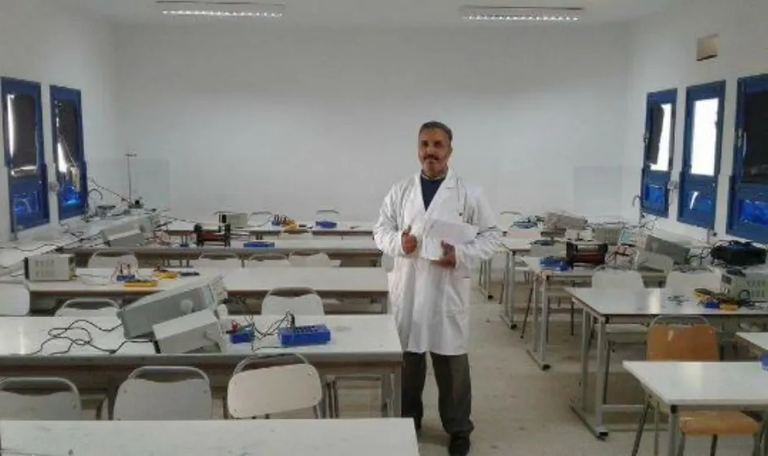
Hello to all the members of the community. I have just presented an experimental activity, carried out in class with my students, to explain the phenomenon of damped free electrical oscillations in a series RLC circuit.
The electrical circuit consists of an ideal voltage generator of fem (E=6V), an initially discharged capacitor (C), a resistor (R), a coil (L,r) and a switch, as shown in the following picture:
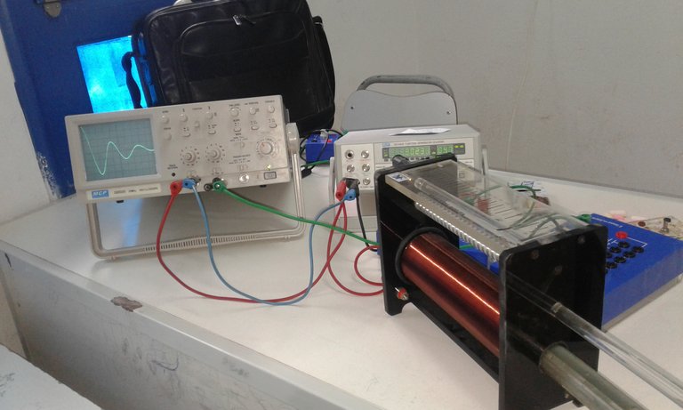
#Source image: photo taken by my mobile phone
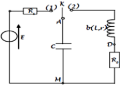
🔴Step 1: Switch (K) is closed in position (1): the capacitor is charged.
🔴Step 2: Once the capacitor is fully charged, switch (K) is turned to position (2). The voltages across the capacitor and the resistor are displayed simultaneously on the oscilloscope.
🌓🌲Results
The curves obtained have the following appearance:
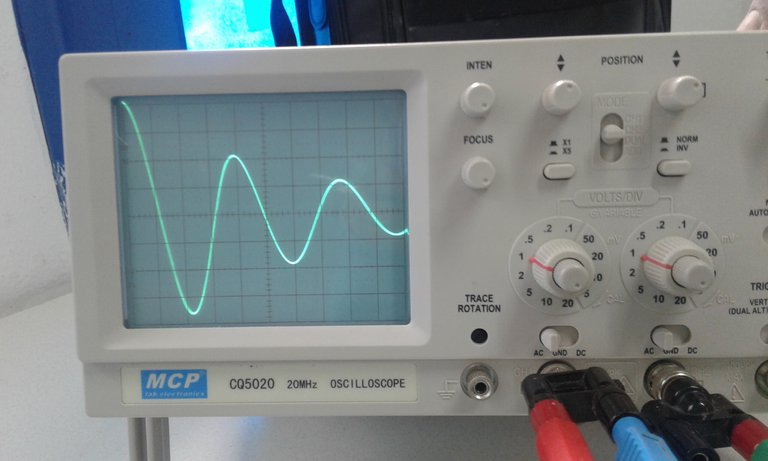
Electrical voltage across the capacitor - (pseudo-periodic regime)
#Source image: photo taken by my mobile phone
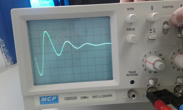
Electrical voltage across the resistor - (pseudo-periodic regime)
#Source image: photo taken by my mobile phone
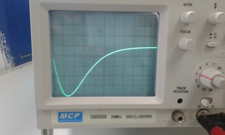
Electrical voltage across the resistor - (aperiodic regime obtained when increasing (R))
#Source image: photo taken by my mobile phone
🌓🌲Interpretation
(K) in position 2: the capacitor has stored electrical energy since the beginning, it discharges through the resistors (R+r) and behaves like a generator delivering a current of intensity (i).
The variation of this current (i), causes the creation of an induced current in the coil, which opposes this variation (according to the law of LENTZ) and consequently a magnetic energy is created inside this coil.
The electrical oscillations observed are called damped free oscillations in the pseudoperiodic regime, which result from the mutual exchange between the electrical energy at the capacitor and the magnetic energy at the coil, and that the electrical current changes circulation twice per pseudoperiod.
These oscillations are damped because their amplitudes decrease with time due to the Joule effect loss of energy through the resistors of the RLC circuit.
These oscillations are called free oscillations because they occur in the absence of a generator.
🌓🌲Remarks
We vary (R) :
📣 If (R) increases, then the number of oscillations is reduced and we obtain either the aperiodic regime or the critical regime: (no oscillations).
📣 Ri (R) decreases, then the number of oscillations increases and the regime obtained is a pseudo-periodic regime.
📣 The variations of (L) and (C) influence the pseudo-period and do not affect the number of oscillations.
🌓🌲Mutual exchange of energy
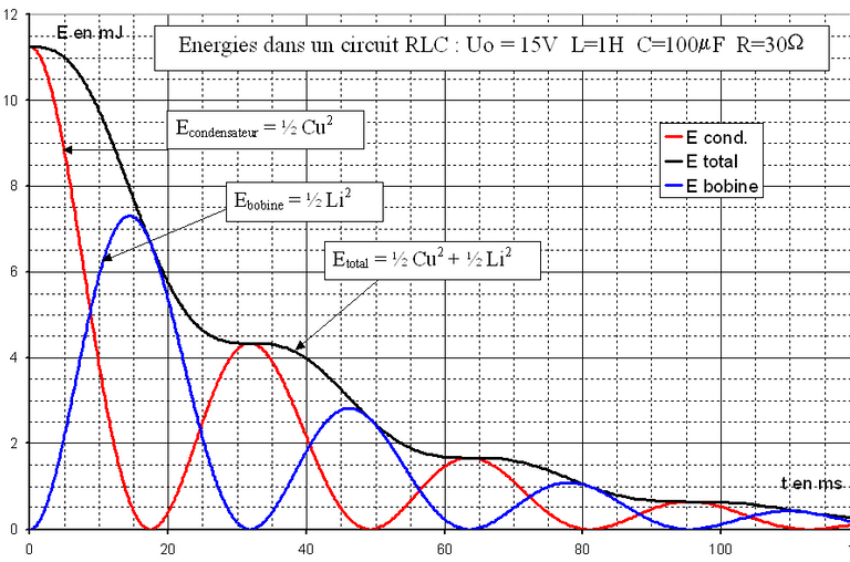
Source image: https://tse3.mm.bing.net/th?id=OIP.7Co4UA2zTuHzXEqTILQXjgHaE9
📣Thank you to all members of the Hive community and to all those who read and vote or comment on this scientific content.🌲
Version Française
🌓🌲Introduction
Bonjour à tous les membres de la communauté. Je viens de présenter une activité expérimentale, réalisée en classe avec mes élèves, pour expliquer le phénomène des oscillations électriques libres amorties dans un circuit RLC en série.
🌓🌲Activité
Le circuit électrique est constitué d'un générateur de tension idéal de fem (E=6V), d'un condensateur (C) initialement déchargé, d'une résistance (R), d'une bobine (L,r) et d'un interrupteur, comme le montre l'image suivante :
#Image source : photo prise par mon téléphone portable
🔴Etape 1 : L'interrupteur (K) est fermé en position (1) : le condensateur se charge.
🔴Etape 2 : Une fois le condensateur complètement chargé, l'interrupteur (K) est mis en position (2). Les tensions aux bornes du condensateur et de la résistance sont affichées simultanément sur l'oscilloscope.
🌓🌲Résultats
Les courbes obtenues ont les allures suivantes :
Tension électrique aux bornes du condensateur-(régime pseudo-périodique)
#Image source : photo prise par mon téléphone portable
Tension électrique aux bornes du resistor-(régime pseudo-périodique)
#Image source : photo prise par mon téléphone portable
Tension électrique aux bornes de la résistance - (régime apériodique obtenu en augmentant (R)).
#Image source : photo prise par mon téléphone portable
🌓🌲Interprétation
(K) en position 2 : le condensateur a stocké de l'énergie électrique depuis le début, il se décharge à travers les résistances (R+r) et se comporte comme un générateur délivrant un courant d'intensité (i).
La variation de ce courant (i), provoque la création d'un courant induit dans la bobine, qui s'oppose à cette variation (selon la loi de LENTZ) et par conséquent une énergie magnétique est créée à l'intérieur de cette bobine.
Les oscillations électriques observées sont appelées oscillations libres amorties en régime pseudopériodique qui résultent des échanges mutuels entre l'énergie électrique au condensateur et l'énergie magnétique à la bobine, et que le courant électrique change de circulation deux fois par pseudopériode.
Ces oscillations sont amorties car leurs amplitudes diminuent avec le temps en raison de la perte d'énergie par effet Joule à travers les résistances du circuit RLC.
Ces oscillations sont appelées oscillations libres car elles se produisent en l'absence de générateur.
🌓🌲Remarques:
Nous faisons varier (R) :
📣 Si (R) augmente, alors le nombre d'oscillations est réduit et nous obtenons soit le régime apériodique, soit le régime critique : (pas d'oscillations).
📣 Si (R) diminue, alors le nombre d'oscillations augmente et le régime obtenu est un régime pseudo-périodique.
📣Les variations de (L) et de (C) influent sur la pseudo-période et n'affectent pas sur le nombres d'oscillations.
🌓🌲Échange mutuel d'énergie
Image source: https://tse3.mm.bing.net/th?id=OIP.7Co4UA2zTuHzXEqTILQXjgHaE9
📣📣Merci à tous les membres de la communauté de la Ruche et à tous ceux qui lisent, votent ou commentent ce contenu scientifique.🌲
You are always motivated and persevering. I really appreciate what you produce and your students too.
very important information, thank you for the effort you have put in presenting such content.
Congratulations @habibh! You have completed the following achievement on the Hive blockchain and have been rewarded with new badge(s):
Your next target is to reach 400 upvotes.
You can view your badges on your board and compare yourself to others in the Ranking
If you no longer want to receive notifications, reply to this comment with the word
STOPCheck out the last post from @hivebuzz:
Support the HiveBuzz project. Vote for our proposal!