Radio frequency with plasma equivalent circuit transformer model-
The equivalent circuit of a radio frequency (RF) plasma with the transformer model can be represented as follows:
   Lp       Cp
-------//\/\/\/\--------       **Plasma**
       |        |
      Cin      Cout
       |        |
      Rg        |
       |        |
--------        |
|      |        |
|      |        |
|      |        |
|      |        |
|      |        |
|      |        |
--------        |
      |
     Rl
      |
     Gnd
where:
Lp: inductance of the RF transformer
Cp: Primary winding capacitance of the RF transformer
Cin: Input matching capacitance
Cout: Output matching capacitance
Rg: Generator resistance
Rl: Load resistance
Gnd: Ground
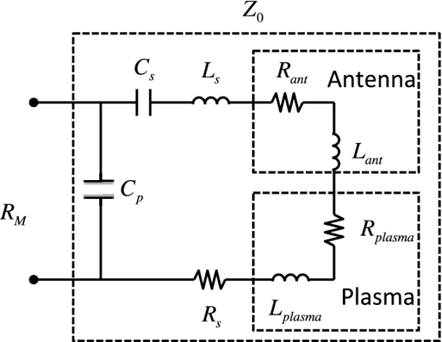
The RF transformer: is used to match the impedance of the plasma to that of the generator and the load. The input matching capacitance (Cin) and output matching capacitance (Cout) are used to further optimize the impedance matching. The generator resistance (Rg) represents the internal resistance of the RF power generator. The load resistance (Rl) represents the equivalent resistance of the plasma.
The capacitance: and inductance values of the circuit elements depend on the frequency of the RF power and the physical properties of the plasma.
This equivalent: circuit can be used to analyze and optimize the performance of the RF plasma system, such as the power transfer efficiency, the plasma impedance matching, and the plasma heating efficiency.

0
0
0.000
0 comments